A print is weaker across its layers: the numbers
Bambu Lab tests each filament along the layers (X-Y) and across them (Z). Across them, impact strength drops for every material in the table, to as little as 2.8 kJ/m² for PPS-CF. Load the part along its layers, and tell us which way the load runs.
- X-Y and Z figures for 12 filaments, same ISO tests
- 8 of them on our most popular list
- We orient each part to its load
- Largest part 360 x 360 x 360 mm (340 x 320 x 340 mm in carbon-fibre and heated-chamber materials)
Why X-Y and Z differ
FDM builds a part from lines of molten plastic, one layer on top of the last. Within a layer, each line fuses with its neighbours along its whole length. Between layers, the new layer bonds to one that has already started to cool. That bond is the weak plane.
Load that runs along the layers is carried by continuous lines. Load that pulls the layers apart, or bends the part so a layer opens, is carried by the bond. Every datasheet here gives both: X-Y for along the layers, Z for across them.
X-Y against Z, filament by filament
Figures from Bambu Lab's datasheet for each filament, measured on test specimens. Bambu gives them "for design reference and comparison only"; a printed part also depends on its shape, walls and orientation. Impact strength by ISO 179, bending modulus by ISO 178.
| Filament | Impact X-Y (kJ/m²) | Impact Z (kJ/m²) | Bending modulus X-Y (MPa) | Bending modulus Z (MPa) | Our status |
|---|---|---|---|---|---|
| PLA Basic | 26.6 | 13.8 | 2,750 | 2,370 | most popular |
| PETG HF | 31.5 | 10.6 | 2,050 | 1,810 | most popular |
| TPU for AMS | 124.3 | 9.6 | not published | not published | most popular |
| PPA-CF | 41.7 | 4.3 | 9,860 | 3,240 | most popular |
| PPS-CF | 27.8 | 2.8 | 7,160 | 2,460 | most popular |
| PET-CF | 36.0 | 4.5 | 5,320 | 2,210 | most popular |
| PC FR | 55 | 8.0 | 1,890 | 1,660 | most popular |
| ASA Aero | 32.0 | 3.4 | 1,510 | 1,220 | most popular |
| PA6-CF | 40.3 | 15.5 | 5,460 | 2,240 | ordered in |
| PAHT-CF | 57.5 | 13.3 | 4,230 | 1,820 | ordered in |
| PC | 34.8 | 9.0 | 2,310 | 1,620 | ordered in |
| ASA | 41.0 | 4.9 | 1,920 | 1,650 | ordered in |
Impact across the layers is where the gap is widest. PPS-CF keeps 2.8 of its 27.8 kJ/m², PPA-CF 4.3 of 41.7, ASA Aero 3.4 of 32.0. TPU for AMS falls from 124.3 to 9.6.
Stiffness drops less. PLA Basic keeps 2,370 of its 2,750 MPa across the layers; the carbon-fibre materials lose more, PPA-CF from 9,860 to 3,240 MPa.
"Most popular" are the materials we print most; they usually take 1-3 working days on average after you approve the price. "Ordered in" materials are sourced for the job, and the quote gives the time.
Design rule: load along the layers
- Find the main loadWhich way does the part get pulled, bent or hit in use? That direction should run along the layers.
- We choose the build directionA part has one build direction. We orient the part so the main load runs along the layers.
- Split what cannot be orientedIf loads come from two directions, one of them crosses the layers. Decide which matters more, or design the part in two pieces joined with screws.
- Pick the material for Z, not only X-YIf a load must cross the layers, compare the Z column. PA6-CF (15.5 kJ/m²), PLA Basic (13.8) and PAHT-CF (13.3) keep the most impact strength across them in this table; PPS-CF (2.8) and ASA Aero (3.4) the least.
- Tell us the loadSay in the enquiry where the part is held and where the force goes. A sketch with an arrow is enough.
Brackets, clips and hooks
- BracketsAn L-bracket printed with the L flat on the bed keeps both legs along the layers. Printed standing, the upright leg bends across them.
- Snap clipsThe arm that flexes should lie in the layer plane. A clip arm printed upright can split along a layer line.
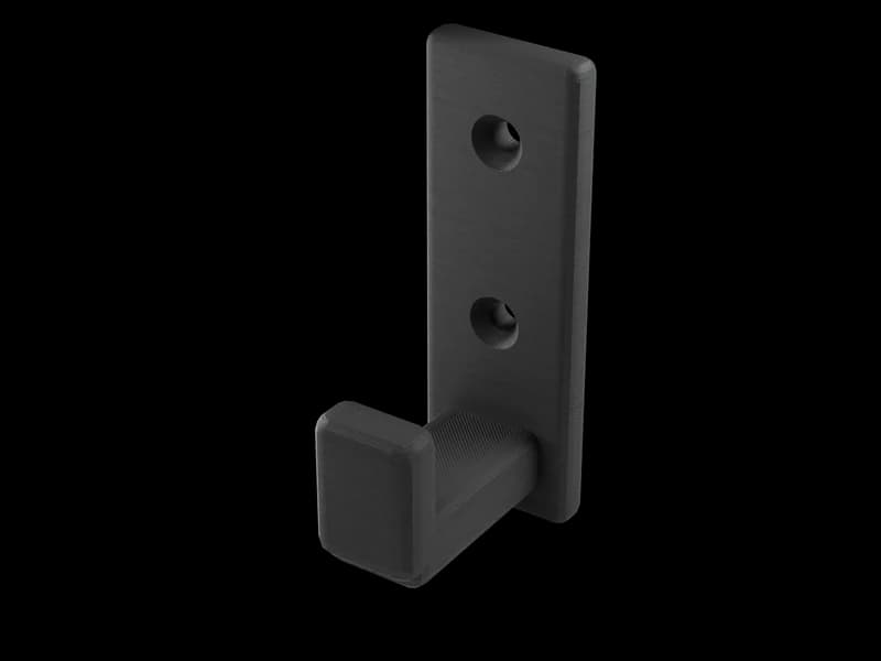
- HooksPrint the hook lying down, so the curve that carries the weight runs along the layers. A hook printed upright can open at the layers under load.
- Screw bosses and insertsA screw pulls along its boss. If the boss stands upright, the pull runs across the layers: give it a wider base, or turn the part.
When FDM is not the answer
Some parts take load from every direction and cannot be oriented or split: a part that spins, a hinge loaded both ways, a part hit from any side. FDM always leaves a weak direction. A moulded or machined part, or a powder-bed print, is closer to equal strength in every direction.
We print FDM only. If your part needs the same strength every way, a person says so when the file comes in, before you pay.
Questions
How much weaker is a 3D print across its layers?
It depends on the material. In Bambu Lab's impact tests, PLA Basic gives 13.8 kJ/m² across the layers against 26.6 along them; PPS-CF 2.8 against 27.8. The table has all 12.
Is carbon-fibre filament stronger in Z?
Not in impact. PPA-CF, PPS-CF and PET-CF give 4.3, 2.8 and 4.5 kJ/m² across the layers, less than PLA Basic's 13.8. Along the layers they are stiffer.
Which material is toughest across the layers?
Of the 12 here, PA6-CF at 15.5 kJ/m², which is ordered in. Of our most popular materials, PLA Basic at 13.8 and PETG HF at 10.6.
Do you give a safety factor?
No. The figures are Bambu Lab's test-specimen values, for design reference and comparison only. Tell us the load, and a person says whether FDM is the right process.
How do you orient a part?
So the main load runs along the layers. Tell us where the part is held and where the force goes.

A part that carries load?
Send the file and mark where the force goes. A person replies with a price in 3 hours on average on workdays.