Check the AI's file before you print it
A file from an AI model can be valid, closed, the right size, and still wrong. In our own test, all four misses listed below were in files a slicer would have accepted without a warning. These are the checks worth running before you send a file, in the order they matter, with those misses as examples. A person here opens every file before a price.
- Units, one solid, size, walls, fits, layers, overhangs, the brief
- Largest single part 340 x 320 x 340 mm
- Tolerance ±0.5% of the size, minimum ±0.5 mm
- A person checks every file before a price
Why a valid file is not a checked file
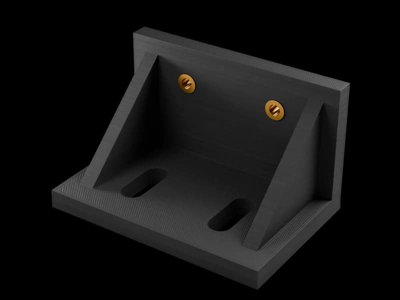
Slicers and repair tools mostly check one thing: is this mesh closed and consistently oriented. That catches a generated STL with holes in its surface, and it is worth doing. It cannot catch a hole in the wrong place, a plate the wrong way up, or a connector that has nowhere to go. On 14 October 2026 we had two AI models draw the same bracket and enclosure from one brief; the files they exported were valid closed solids, and still the four misses listed below got into the files or the brief. All four would have printed.
So the list below runs from the cheap checks that fail loudly to the ones that need you to know what the part is for. Do them in order. Each one takes a minute.
The checks, in order
- Units: millimetres, and the right onesOpen the STL in any slicer and read the bounding box. An STL has no unit; the slicer assumes millimetres. If the part should be 120 mm and the bounding box says 12, 0.12 or 4.72, the script or the export used centimetres, metres or inches. OpenSCAD is unitless too, and an STL from any of the three stores none: the number 40 is 40 mm only because everyone agrees. CadQuery and build123d write millimetres into a STEP file by default. Ask for "all dimensions in millimetres" in the brief and check the bounding box anyway.
- One closed solidOne body, no overlapping shells, no floating pieces, no open edges. A code CAD script can prove this: build123d and CadQuery report whether a solid is valid and how many solids a file holds. A mesh generator cannot, and a generated STL is routinely not watertight. Run the slicer's repair; if it reports open edges after the repair, go back to the source. Our enquiry endpoint measures the first STL of each enquiry on arrival and reports closed: true or false; a person reads that before anything else.
- Size against the printerThe largest part we print in one piece is 340 x 320 x 340 mm. Bigger parts are split and joined, which is a design decision, not a slicer setting. Check the bounding box against the material you want before you ask for a price.
- Walls and small featuresGeneral FDM practice with a 0.4 mm nozzle: a wall thinner than two extrusion widths, about 0.8 mm, may print as a single fragile line or not at all; a hole smaller than the nozzle disappears. The two snap tabs in our test were 2.0 and 1.6 mm thick, the release slots 0.8 mm wide: at the edge of what prints cleanly, and both models' notes flag them. Measure the thinnest wall and the smallest hole in the model, and ask whether each has a reason to be that small.
- Fits against the tolerance we holdWe hold ±0.5% of the size, never tighter than ±0.5 mm. A 12.6 mm bore for a 12 mm sensor has 0.3 mm a side; a 2.5 mm pilot for an M3 self-tapping screw has nothing to spare and is a one-boss test, as both models wrote. A hole prints a little small and a peg a little large. For every surface that mates, ask: what is the clearance, and what happens if it comes out 0.5 mm the other way. If the answer is "it does not fit", change the parameter now.
- Which way the layers run under loadA printed part is weakest across its layers. A clip that flexes, a hook that carries weight, a tab that snaps: each wants to bend along the layers, not pull them apart. In our test one model laid the bracket on its side so the latch bends in the layer plane and needs no support; the other printed the plate face down for spring strength and accepted local supports. Both were defensible; both said which they chose and why. The Z-axis guide linked below has the figures by material.
- Overhangs and supportA round hole with a horizontal axis droops at the top; a teardrop does not. A horizontal flexure prints as an overhang and needs support in exactly the place you cannot clean. Look at the part in the orientation it will print and ask what hangs in the air. Where the AI changed a shape to avoid support, it should say so in its notes; where it did not, ask it.
- The brief's own ambiguitiesThe model reads what you wrote, not what you meant. Read its assumptions list and check each one against the real part in your hand. If the model wrote no assumptions, ask for them before you print; a model that cannot name an assumption has made one you will find at the rail.
Four misses from a valid file
From our two-model test on 14 October 2026. Every file involved was one valid closed solid at the time of the miss.
- The teardrop that was never cutThe brief asked for no support where possible. One model drew the sensor hole as a teardrop so its top would not droop, and three runs exported a plain round hole: in the library's algebra mode, Circle + Polygon had produced two faces and only the circle cut the plate. A check on the hole's shape, not its diameter, found it. A slicer would have printed the round hole and the top would have sagged.
- The USB opening cut in the wrong frameThe 1.7 mm height offset was applied after the sketch had been mapped onto the wall plane, so the opening moved sideways instead of up. Still a valid solid, still a 9.6 x 3.9 mm slot in a 2 mm wall. A receptacle placed where the board said it would be overlapped the wall by 93 mm³, and that overlap check caught it.
- The connector that would not fit behind the nutNothing in the brief mentioned a cable. Geometry did: with the plate 30 mm in front of the rail and a 4 mm nut behind it, about 30 mm stays free to the rail channel, and a straight M12 plug needs more. One model noticed, and wrote: angled connector or cable sensor led out sideways. No file check finds this; a person who has mounted a sensor does.
- The ambiguous 30 mmThe brief said the sensor axis is perpendicular to the rail face and 30 mm in front of it. A line normal to a plane has no distance from it. Both models flagged it and both took the plate's mid-plane at 30 mm. Right call; the brief was wrong, and a file made from a wrong brief passes every geometry check.
Repairing a generated STL
For a file from a mesh generator (text-to-3D, image-to-3D), the slicer's repair is the first move and usually works: it closes small holes and fixes flipped triangles. What it cannot fix is overlapping shells that were never one body, or a shape the generator guessed; our photo-to-model guide covers why a generated mesh carries no controlled size.
For a file from code CAD, do not repair the mesh. Go back to the script, ask for one body, and re-export. A repaired STL hides the error the script still has, and the next export brings it back.
Then send it
The quote form takes STEP, STP, STL, 3MF or OBJ in millimetres, up to 25 MB each; email takes the same, or a link. A person opens the file before any price. If something will not print as drawn, you hear what and why first. If it passes, you get a price for one piece in 3 hours on average on workdays, and we suggest printing that one before a batch.
Where FDM is the wrong process for the part, a fit tighter than ±0.5 mm, a smooth moulded face, a figurine with 0.1 mm detail, we say so and say what would work.
Questions
Checked by the druckworks workshopUpdated
Can you print an AI-generated STL?
Usually, once it is closed. Our endpoint measures the mesh on arrival; a person then checks size, walls and fits and tells you what, if anything, needs changing before a price.
How do I check an STL before printing without CAD software?
Any free slicer shows the bounding box, warns about open edges and offers a repair. That covers units and closure. Fits and load direction need you to know what the part is for; the list above walks through them.
What is the minimum wall thickness you print?
We publish no single figure, because it depends on the material and the feature. General FDM practice with a 0.4 mm nozzle is about 0.8 mm for a wall that must hold. Send the file and a person tells you where it is thin.
Should I repair the STL or fix the script?
Fix the script when there is one. A repaired mesh hides a bug the next export brings back. Repair only files from mesh generators, where there is no script.
Will the AI's fits work with your tolerance?
If the clearance in the file survives ±0.5% of the size, minimum ±0.5 mm, in both directions. A 0.3 mm clearance a side on a 12 mm bore does; a 0.1 mm clearance does not.
Do you check the file before I pay?
Yes. Nothing is paid until a person has opened the file and sent a price. If it will not print as drawn, you hear that first.

Send the file, we check it first
STEP or STL in millimetres, from the form or by email. A person opens it and replies with a price in 3 hours on average on workdays.